
I am busy building a dome controller to replace the Foster Systems unit. I call it BrewSpinDome, an Arduino based controller with a more precise position sensor (2 to 3 times more precise). I use the existing Home sensor.
Mark I Position Sensor
In my first attempt, I used an IR reflective sensor from Adafruit. It has an infrared emitting LED and a phototransistor (photodiode?) to detect reflected light. The two pieces are tilted slightly; the presence of a dark or light spot in front of the sensor changes the output voltage.
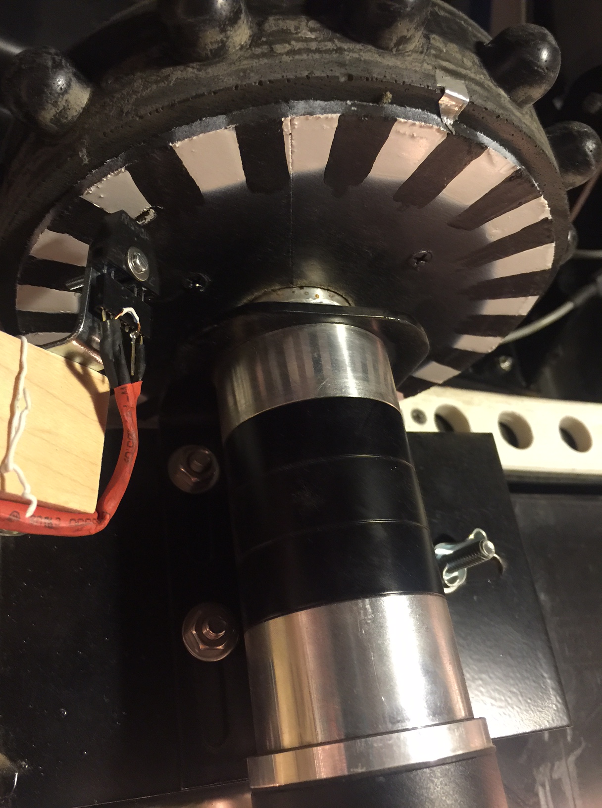
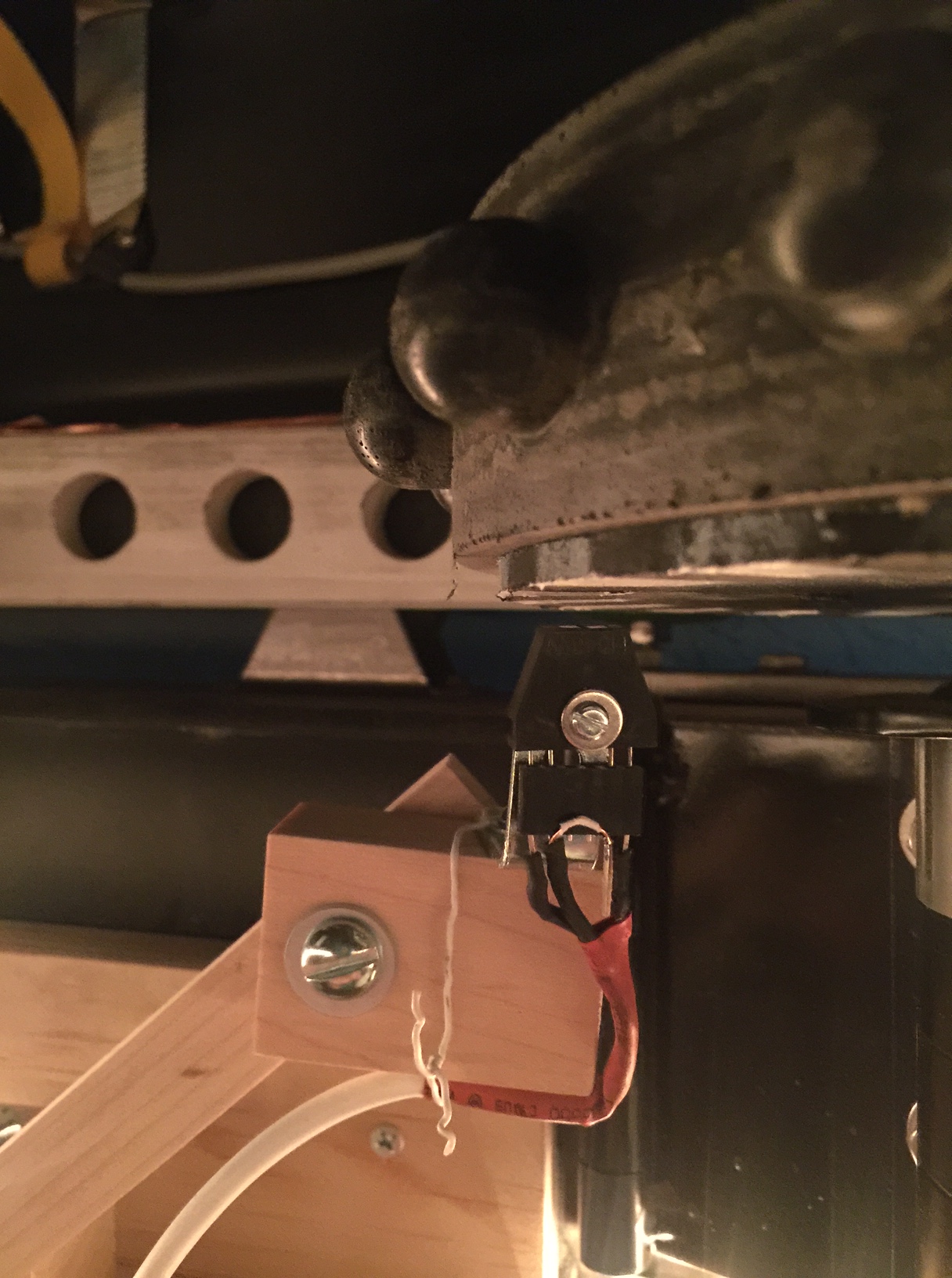
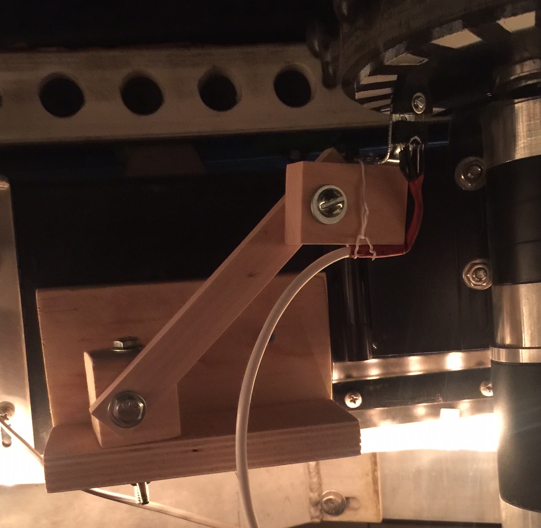
The images below show the sensor wheel mounted below the dome rotation gear, with the sensor positioned to detect the dark and white zones. The mounting bracket allows positioning of the sensor precisely under the wheel. It turns out the sensor works best when it is roughly 5mm from the wheel.
An oscilloscope shows the sensor output as the blue line. The yellow trace shows the Arduino receiving interrupts when the sensor switches states.
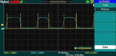
This was working OK; I used this system to start debugging the software. However, I began to see problems; the dome was missing sensor ticks. It turns out the dome gear “wobbles” a bit as it turns. This moves the gear closer to the sensor, so the voltages are not sufficient to get the pulses shown above.
So, back to the drawing board.
Mark II Position Sensor
In this design, I have a toothed wheel under the dome gear. I obtained an IR LED / phototransistor pair from Radio Shack which are positioned so the toothed wheel breaks the beam as it rotates. Hopefully this will generate better pulses.
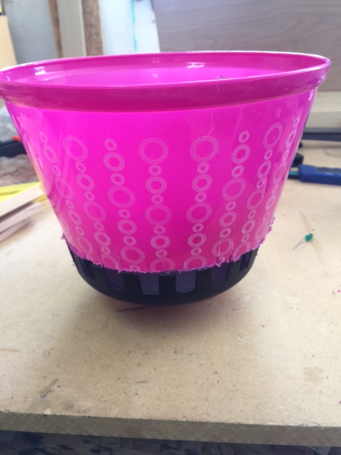
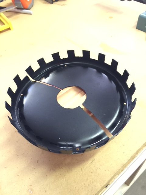
The toothed wheel was created by cutting the bottom of a plastic pail obtained from my standard parts warehouse (Dollar Store). The image shows the original pail on top of the bottom piece which was cut off. I used a Dremel to cut the teeth in the wheel, as well as a central hole and two cuts to facilitate placing the wheel around the axle of the dome gear.
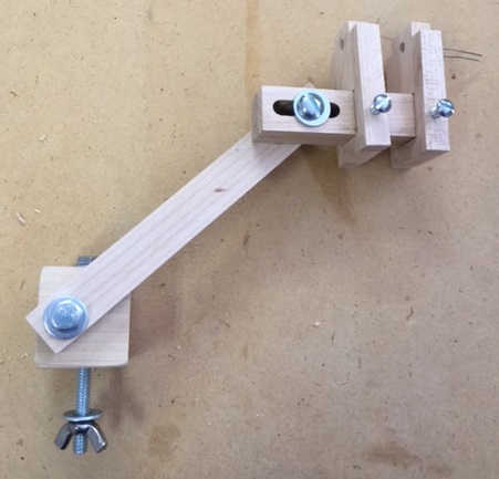
I also modified the mounting bracket as shown to place the IR emitter/detector on either side of the teeth. The two LED holders may be adjusted to get the sensor aligned.
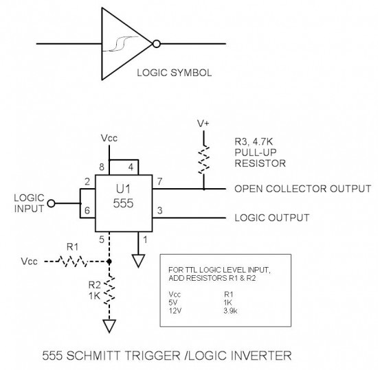
Schmitt Trigger
I also stumbled upon a device known as a Schmitt Trigger, or Schmitt Inverter. It takes my slow-changing pulses and changes them into sharper square pulses. Very nice! I will add this to my circuit. In the Mark I, I was getting multiple interrupts at each transition; I had to add software logic to ignore interrupts for 25-50 milliseconds after receiving one. Maybe this will eliminate that problem.
Is Chatman looking for a driver for the club dome at Ionia? There may be a problem there – as I recall, one of the RS232 chips was blown in the dome communications panel…
What I wrote was not an Ascom driver. It was a standalone small program which would open or close the dome. The code might still be on the dome computer. As I recall, I wrote it as a script on that computer.
The concept was fairly kludgy – you sent “A” or “a” to raise or lower one side of the dome a bit. The “B” / “b” character did the other side of the dome. The timings were not the same; for example, it took perhaps more “A”s to open the shell than “a”s to close it. You had to keep sending the character to get the shell to completely up or down. So, a long string of “A” characters would raise the shell. I had manually worked out the number of “A”s and “B”s required.
There was no sensor to indicate whether the shell was up or down. I think a good plan would be to add sensors to detect when the dome is open or closed.
I recently noticed that Foster Systems is now providing a driver for the Astrohaven; they must have entered into some type of agreement. I don’t know anything about it, just noticed it on their web site.
Good Luck,
brew
Hey Brew! Looks like you’re having fun. Andy Chatman is looking for someone to write a quality Astrohaven clamshell dome ASCOM driver. I said I seem to remember you writing one for the Bigdome years ago. Is that true? If so, do you still have a copy you can send to Andy in Thailand?
Dave