
 When we moved to Arizona from Upstate New York, it was my intention to build a domed observatory. In New York I had a remote roll-off, and was always scared to death that I would close the roof on the telescope. The telescope had to be parked correctly to avoid the roof. I never actually crashed the scope, but I came close a couple of times (I get really stupid late at night:)). I wanted to try a dome, since it would avoid the crashing problem and maybe help with nearby lights, winds, etc.
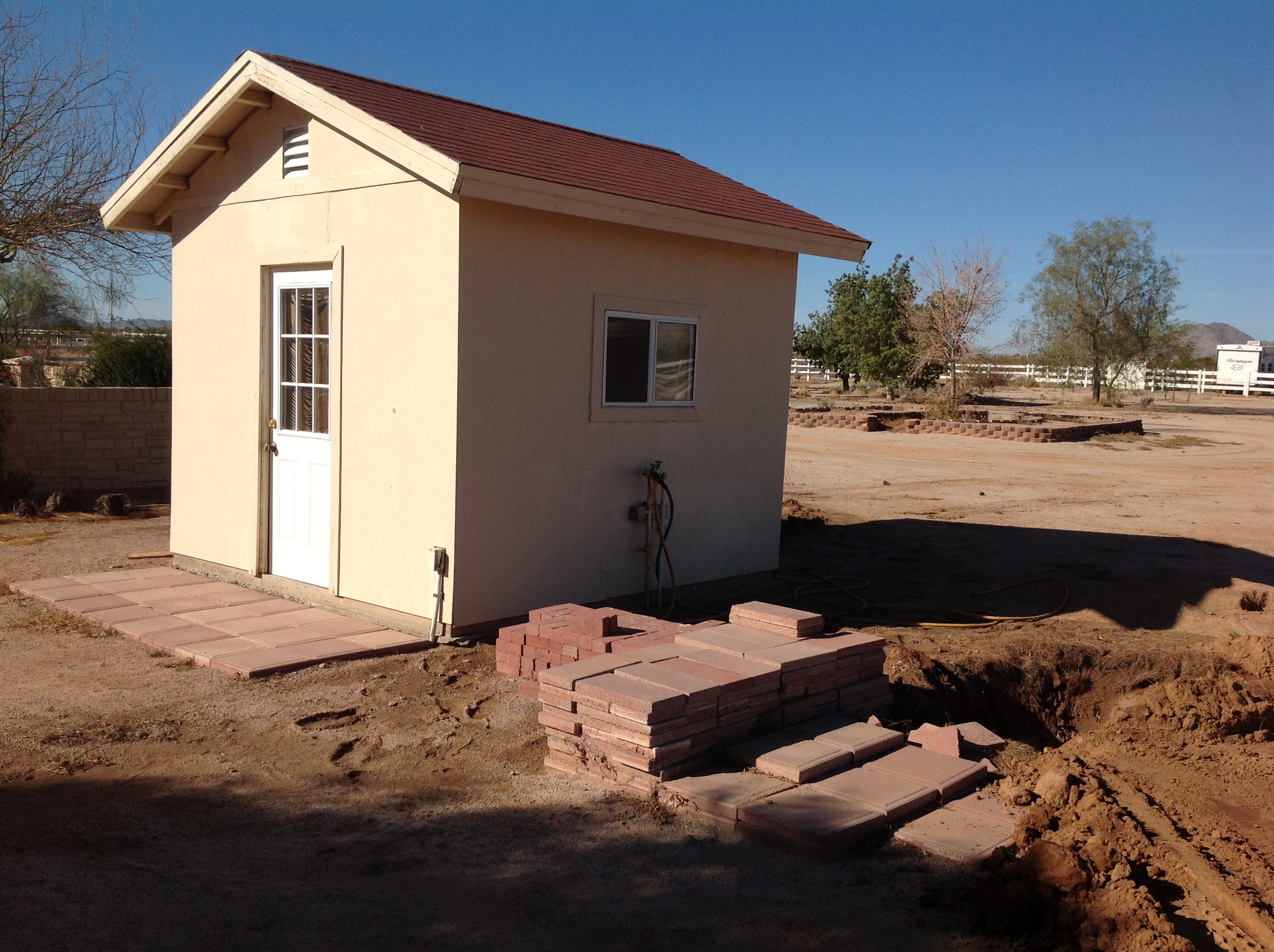
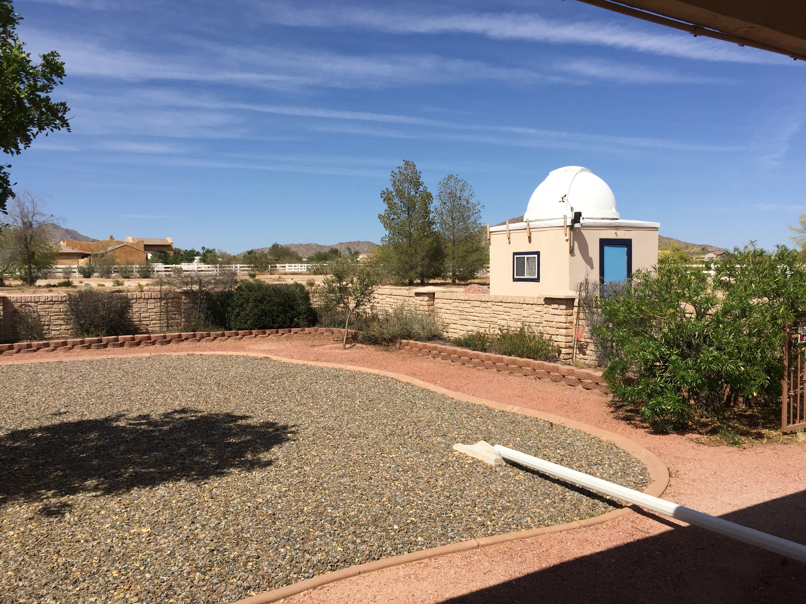
When we bought the house, it happened to have a very nice potting shed built by the previous owner. It had windows, power, and water, and was a perfect size (10′ square) for installing the Exploradome. I took off the existing roof and installed the Exploradome using the kit they provide (aluminum frame, plastic roofing panels). I rented a concrete saw and cut a large square hole (3 feet on a side) in the existing slab for the pier. I dug down about 3 1/2 feet for the pier, and had a truck come and dump concrete in the hole through the doorway using the long spout from the truck.The actual pier is 8 feet long, bolted to 6 J bolts embedded in the concrete. In the end, the pier could have been a bit shorter, perhaps a foot or so. It turns out the Paramount MX and telescopes barely fit in the dome; the scope clears the side walls by about 6 inches.
I tried a number of things to work with the telescope on the crazy tall pier. In the end, I installed a raised floor about 3′ off the floor level. From there I can reach most things on the equipment. I use a small stepladder when it is necessary to reach higher.
|
|
|
|
|
|
|
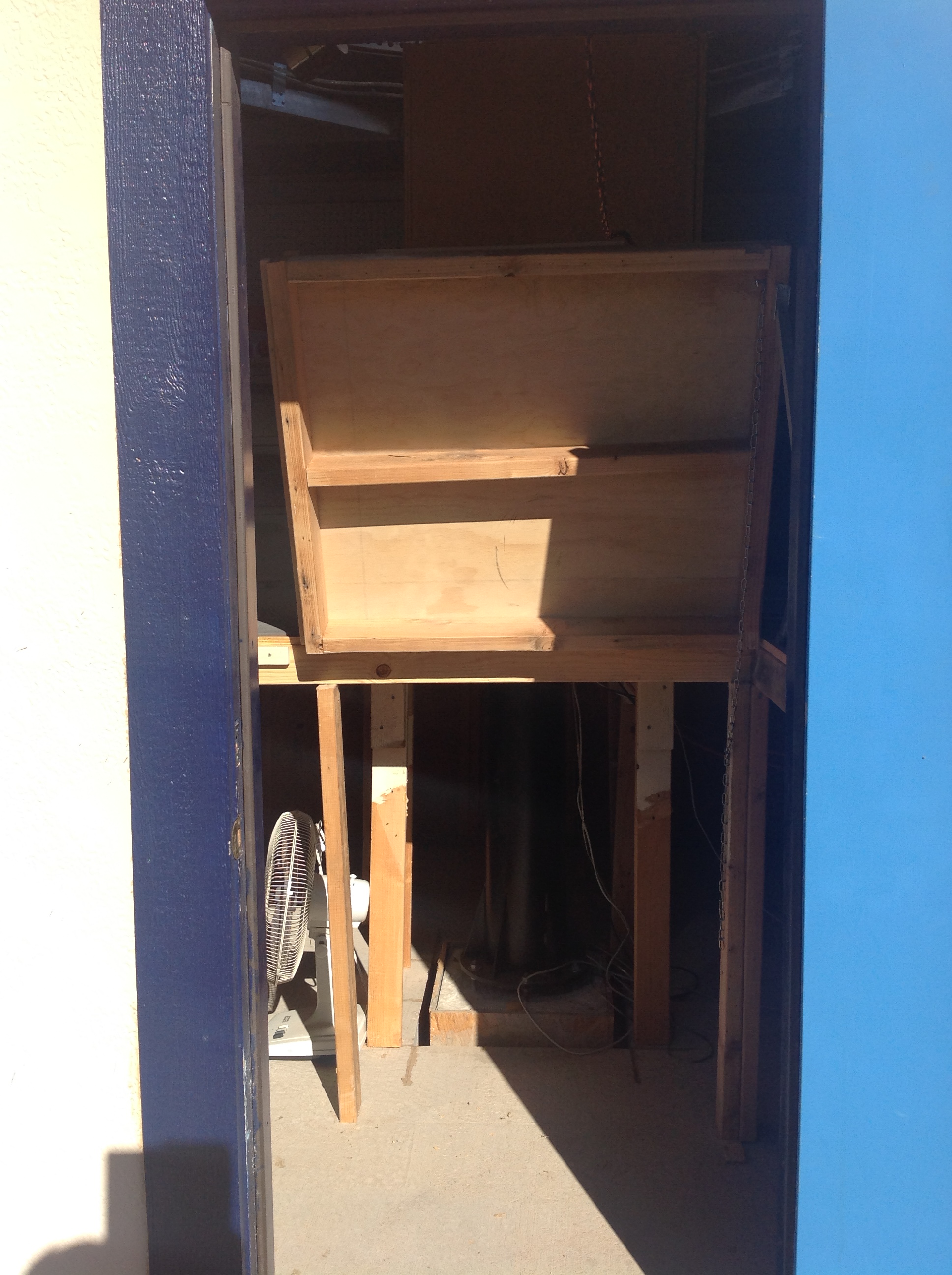
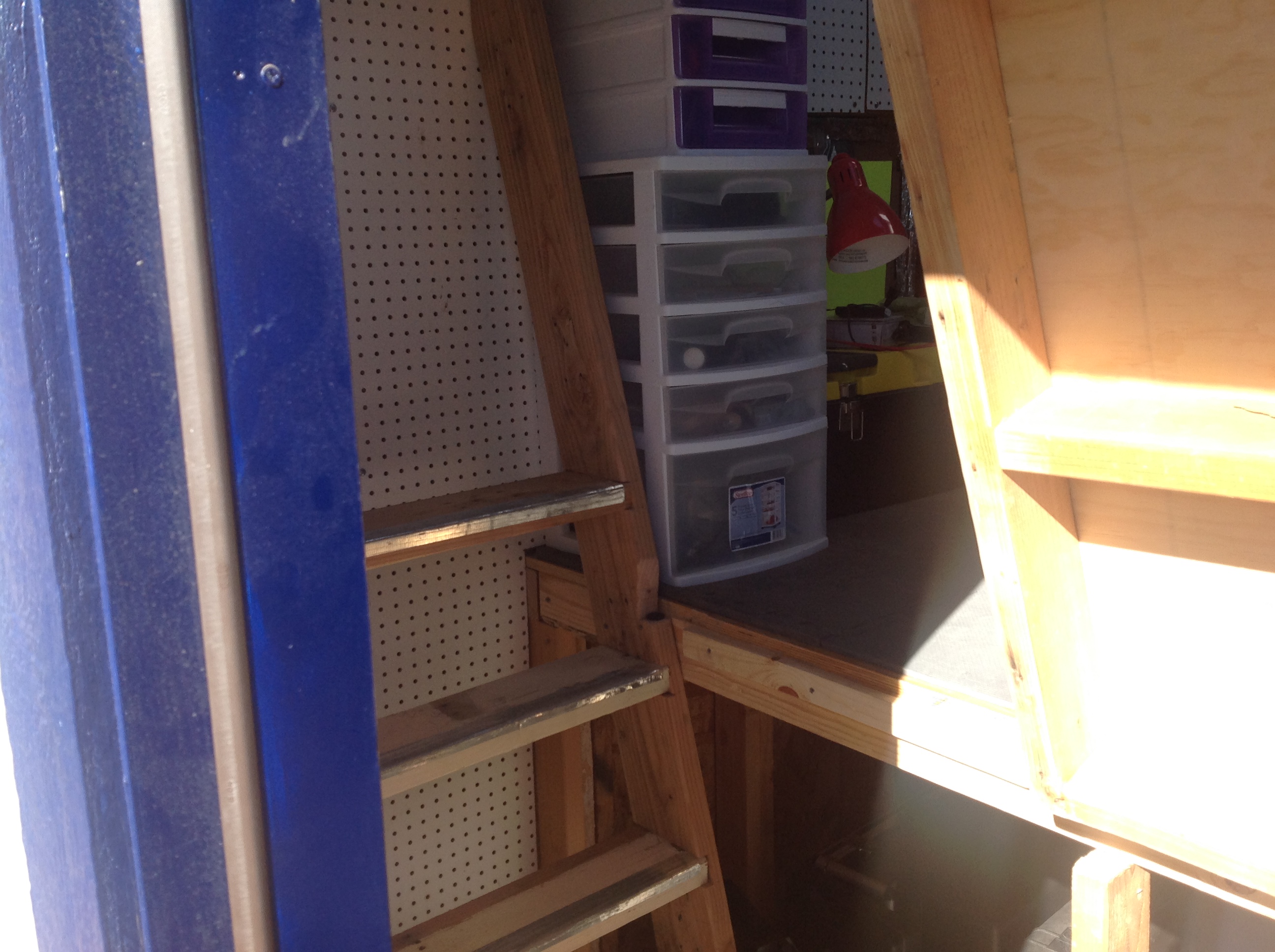
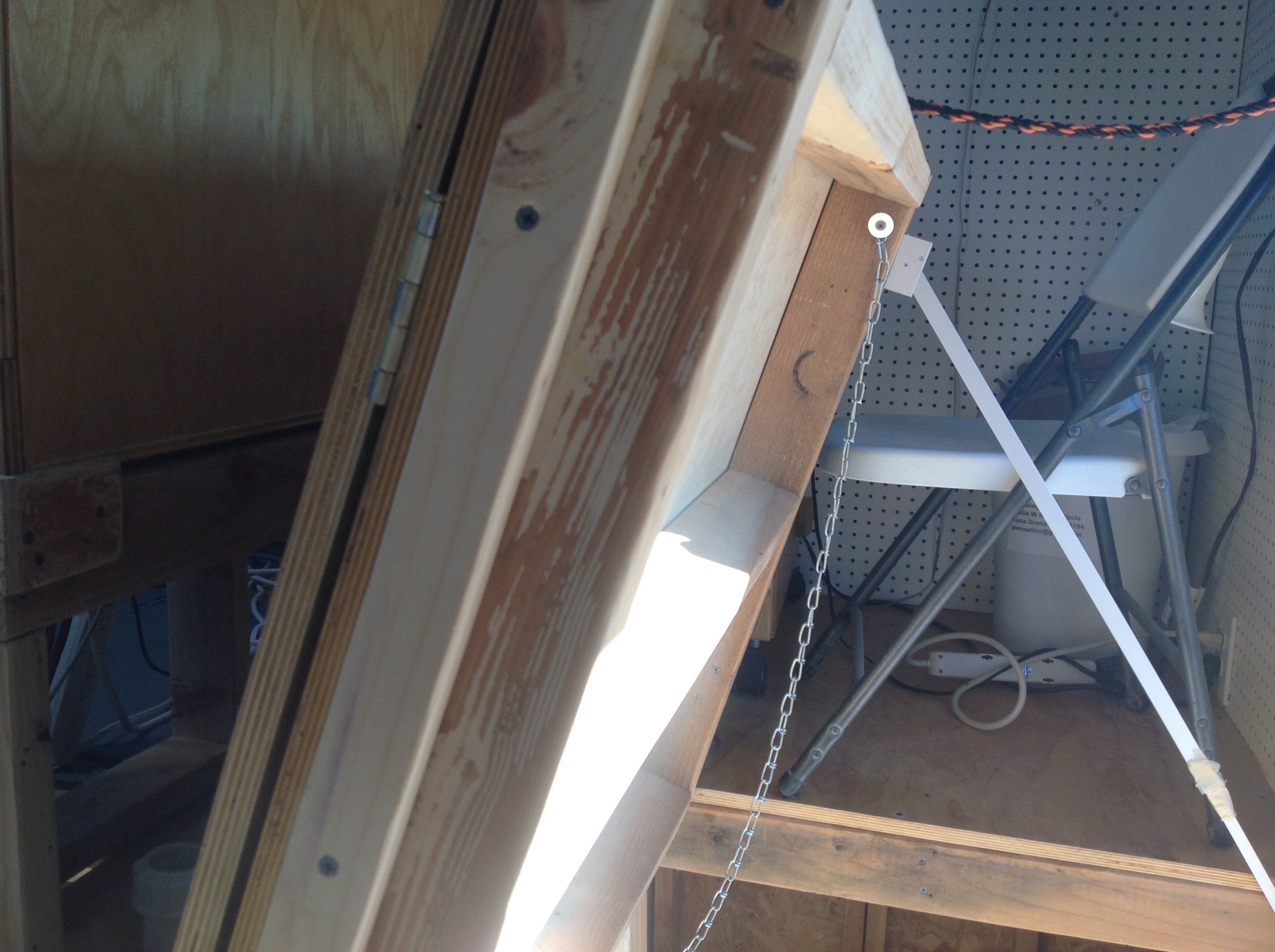
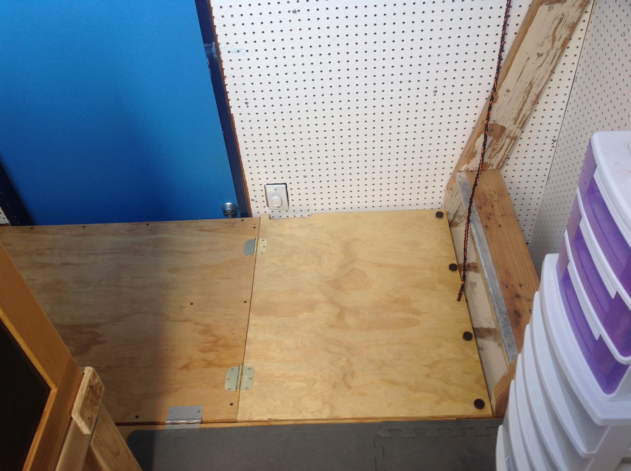
When the door opens, you see the double trap door in the raised position. Walking in, the ladder is on the left. I climb up the ladder, then drop the trap door so I can walk all around.
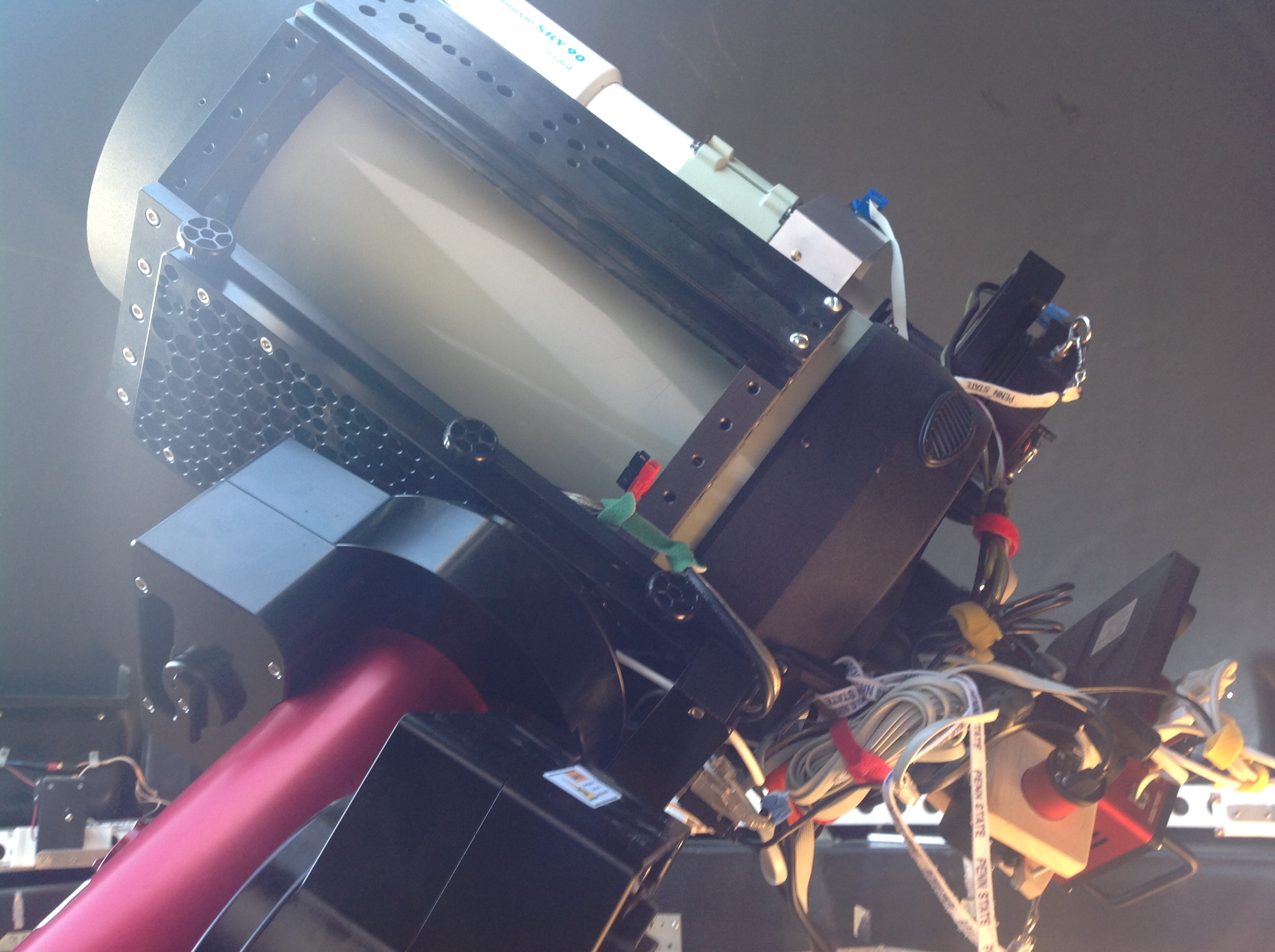
The Paramount MX holds two scope systems:
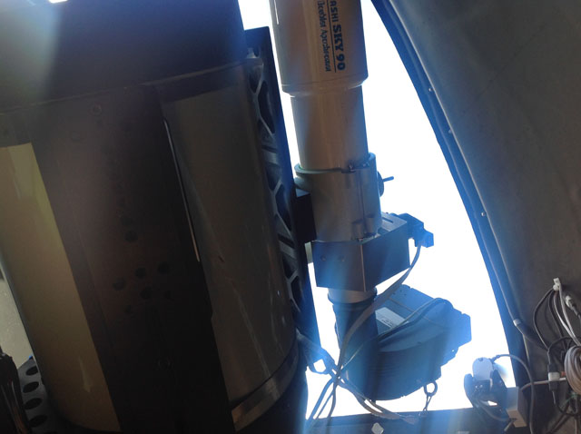
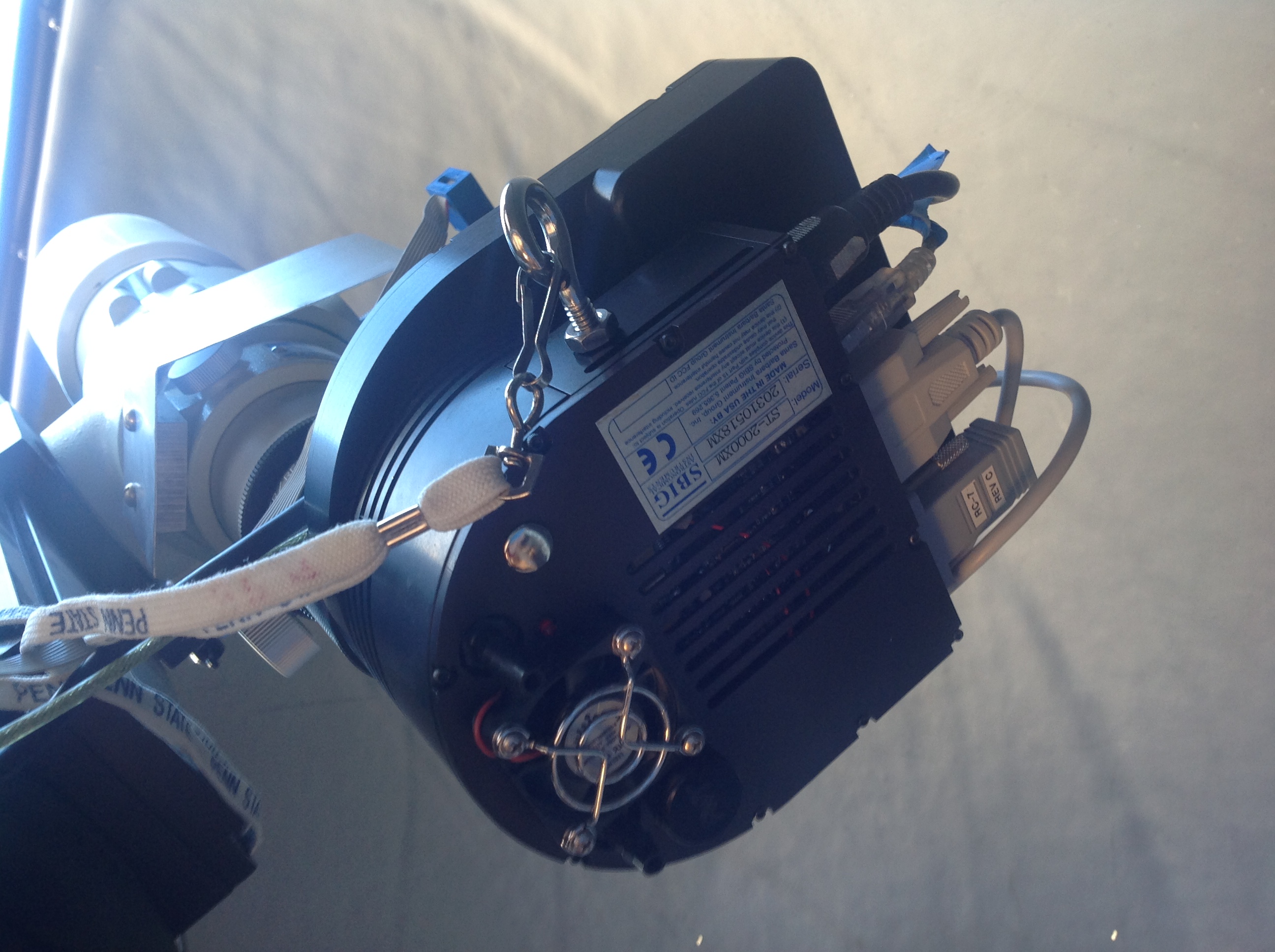
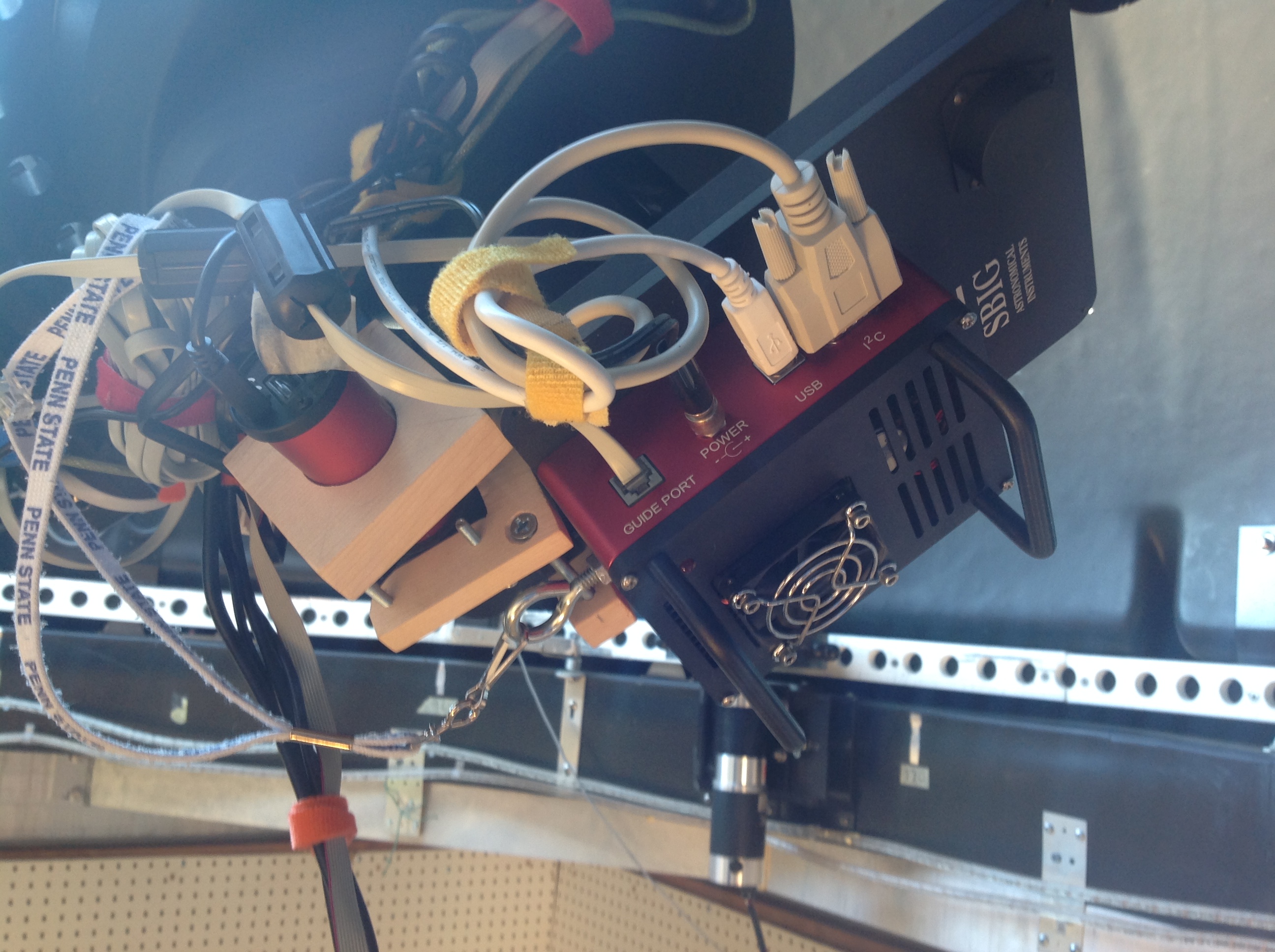
Widefield: Sky90 (now an FSQ106) refractor with SBig ST2000XM camera, 10 position filter wheel. Image scale is 3.7 arcseconds per pixel unbinned. The camera has a second guiding chip so sometimes I can guide (depending on the filter being used). The refractor is mounted on the C11 with a wide Losmandy rail. The camera is a completely threaded mounting. Focusing is through the LazyFocus controller using a Robofocus motor. The mounting of the motor is in its 5th generation, pretty good now.
I also guide using the Edge 11/STF8300 as the guide camera. This requires both scopes to be positioned so they look out of the slit. This usually works, but there are a few positions at the North and South limits where the Edge does not quite see out.
Narrow Field: Celestron Edge 11″ mounted in a Homeyer cradle for stability. Uses an Optec focuser with a SBig STF8300M camera, 8 position filter wheel. Has the STi off axis guiding option. Image scale is 0.40 arcseconds per pixel.
More views
|
|
|
|
|
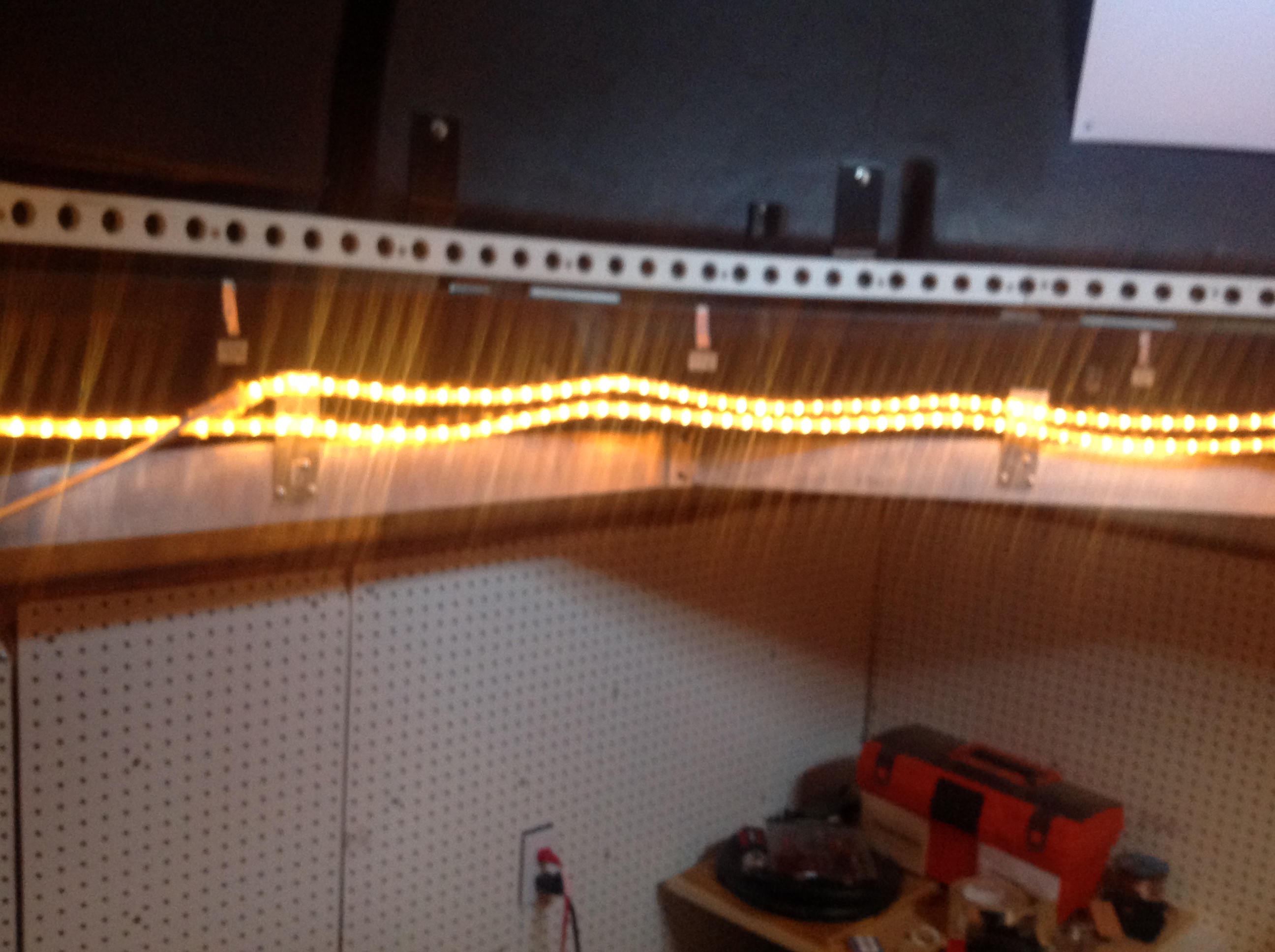 The rope lights are manually controlled by a light switch.
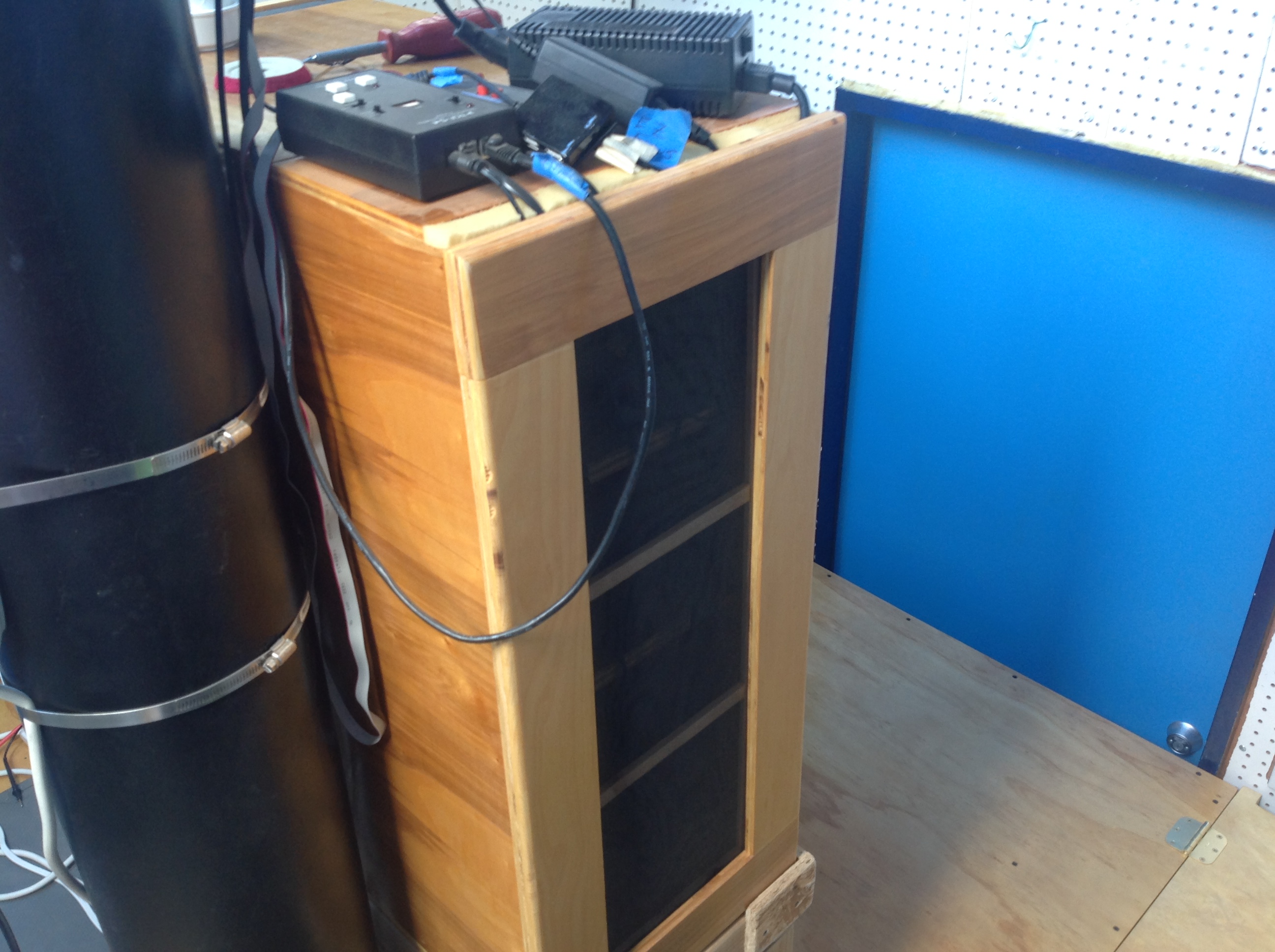 This cabinet contains the electronics required for the mount, cameras, etc. Doors on either end lift off (not hinged). The doors have plastic screen so air can easily flow through the cabinet. Foam around the top edge allows cables to exit while sealing out bugs and dirt. There are also two 3″ holes with foam plugs for power and cables into the cabinet.
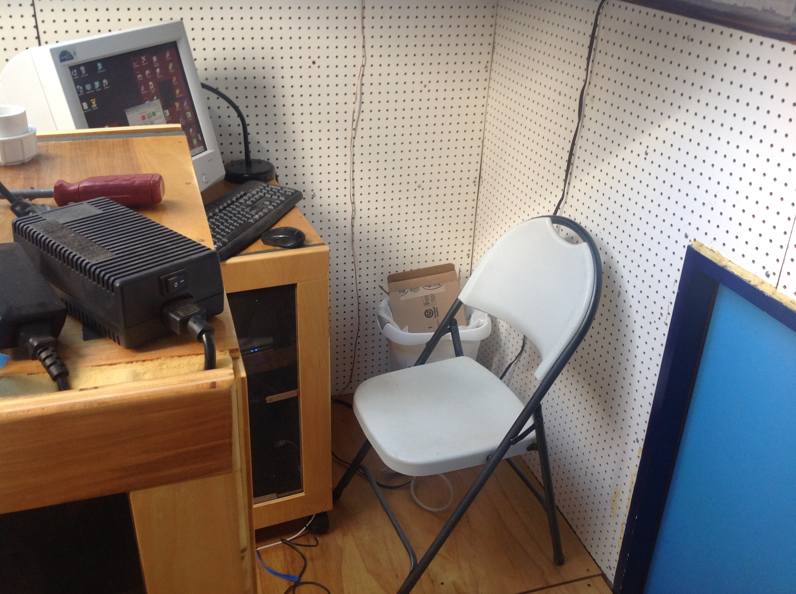 The computer, networking hardware, dome controller, and dome power supply are in the main cabinet (with the monitor on top). Like the electronics cabinet, the front and back doors lift off and have a mesh screen for air flow. 3″ cutouts for cabling are plugged with foam, and foam lines the top door edge so cables are sealed.
Most of the time I work in the house rather than at the observatory computer.
Dome Drive System
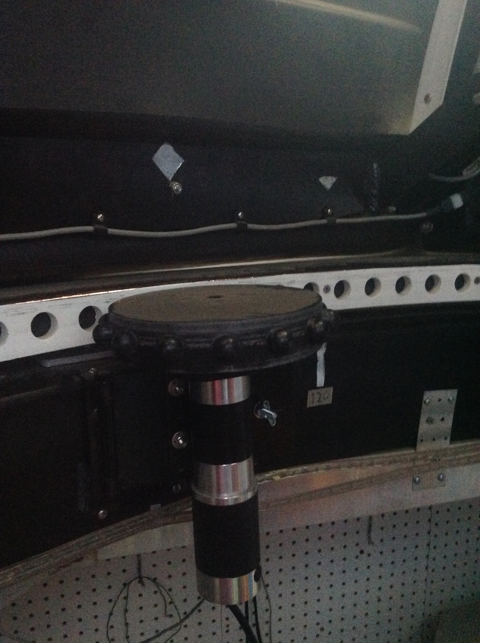
The dome rotates using a large sprocket wheel pushing against the holes in the track. This works very well; it tends to position within 1-2 degrees of the target azimuth, although it will occasionally be off by as much as 3 degrees.
The shutter has been an adventure. The dome is intended to be run by two small batteries, one for rotation and one for the shutter. I immediately managed to kill the batteries somehow, so I run from a power supply. Power to the rotation motor is easy. However, power to the shutter motors is difficult since the dome rotates.
Version 1: I set up a pair of contact metal strips on the fixed part of the dome ring, with corresponding circular “spring” contacts on the dome. The idea was to only get power to the shutter when the dome is in parked position. In that position, the stationary metal strips would make contact with the dome contacts providing power.
This worked poorly at best. The strips tend not make good contact, and tend to catch other things as the dome rotates. Also, it turns out the Foster software gets confused when the shutter loses power, so status is reported incorrectly and open/close movements do not work correctly.
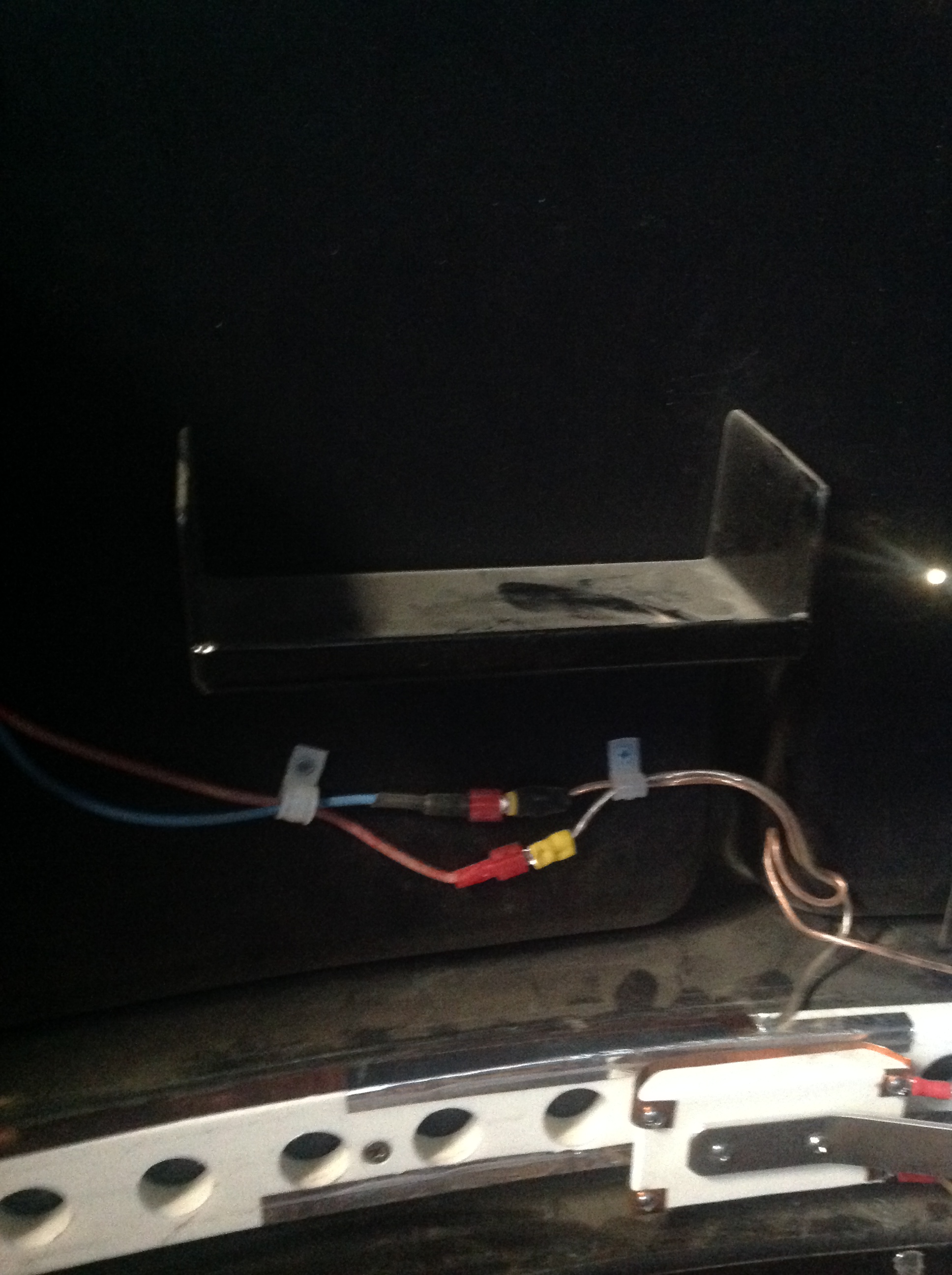
Version 2: My second approach was to put aluminum tape along the inside edge of the track (which moves), and use the “brush” device shown to apply power to the two tape strips. The power is picked up by two wires under the tape. Thus, power remains to the shutter at any rotation angle.
This worked well for awhile, but the tape strips started failing. They are breaking somehow with small “fractures” every 8-12 inches. I theorize that this is due to the track flexing due to the force of the rotation sprocket against the track. I tried patching the tape, but it keeps breaking.
Version 3: I put copper tape from Digikey on the top and bottom edges of the track, not on the face. You can see the copper tape to the left of the brush (I ran out of tape to complete the circle). I built a new brush device which uses a clamping action to make contact with the top and bottom of the track instead of the face. Hopefully if the sprocket is not grinding on the tape it will hold up. Also, the copper tape is a tad thicker than the aluminum.
This works better, but still has the problem of small breaks in the tape. The failure rate is smaller, but I have to go out every 3-4 months and patch the tape, putting 1 inch strips of tape over the breaks. I am hoping that the small pieces will have better flexibility or something, and perhaps lead to fewer failures. If nothing else, I suppose I will eventually have fairly thick layers of copper:).
Version4: Giving up on providing continuous power to the shutter. Glued two copper contacts roughly 6 inches long to the top and bottom of the track. Power is only supplied when the dome is in the Home position. It takes about 20 seconds for the shutter controller to power up and establish Internet connectivity. This has worked much more reliably.
2) Installed insulation and drywall in the observatory. I should have done this in the beginning, but didn’t think it would be that critical. Wow, it gets hot here in Arizona! I also installed a tarp shading the West wall to give it a little shade.
3) Installed an IP network camera so I can check things from inside the house. In particular, sometimes the shutter might not always close right.
4) Developed an Arduino-based temperature probe, with an associated VB.NET program to control the air conditioner in the observatory. This is described here.
5) The Foster Systems shutter controller has consistently had software problems. I finally built my own Arduino based controller with a separate program to control the shutter. I continued to use the Foster system for rotation control, but eventually replaced that with another Arduino based controller.These projects are described in shutter and overall system posts.