
I have tried a variety of devices in an effort to have flat panel flats in the dome. All were failures:
- White cardboard square mounted on dome, lit with lamps below. The flats were slightly tilted since the screen / light / OTA are not aligned well.
- Light boxes. Tried two versions; both failed to provide an even illumination across the surface.
- Electroluminescent panel. It is not white, kind of a green/blue. Hard to get enough intensity in the Red, HAlpha, and SII filters. Cannot control from the computer. Too small for the C11.
- Light table. LitEnergy A2 model, although all the different vendors look identical and are likely produced by the same Chinese factory. Unstable electrically, will change intensity for no reason. Cannot control from computer. LEDs do not stay on, but seem to be “panning” in strips across the surface, requiring longer exposures.
So, here is the next hare-brained approach. The lighting industry has developed LED lighting panels intended to be used as replacements for the typical fluorescent light fixtures. They typically come in 2’x2′ and 2’x4′ sizes so they have the same footprint as the fluorescent fixtures. In addition, some models allow dimming by a wall switch slider.
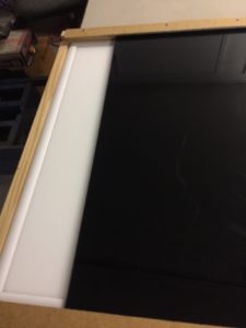
I bought a 2’x2′ model for $45 on Amazon. It is an ASD Edge-Lit Flat Panel, Standard Series, model ASD-ELP22D4040. It is a 40W dimmable panel, Color temperature 4000K, 3400 Lumens. It is nicely solid, unlike the Light Table monstrosity.
Dimming Mechanism
The panels use “standard 0-10V dimming”. There are two sets of wires in the “controller” (looks like the typical ballast box on fluorescent lights). One set is the usual three 110V wires (black, white, and ground). The second set of two wires is for the 0-10V dimming, marked as 0 and +10V.
My original thought was that I should provide a 0-10 V signal on the wires. Wrong! The controller is sending the 10 volt signal – I just need to put a resistor across the wires. If I short the wires together the panel is off. Put a small (100 Ohm) resistor across the wires and the display is dim. A large resistance (leave the wires separated) and the display is on full brightness.
Even at the dimmest settings the panel is too bright, especially for binned flats. I inserted two sheets of smokey gray acrylic plastic over the panel. Each sheet is about 3/16 inch thick, retrieved from the local plastic company’s scrap bin. The sheets attenuate the light nicely, so even 4×4 binned Luminous flats work well.
Solution
I set up a simple Arduino Uno ($10 knockoff) which adjusts 2 digital 10K potentiometers connected in series. The light controller wires are connected to the 2 pots. The Arduino can set each pot in steps of 0-255. So, for a dim light I set the first pot to something like 10, and the second pot to zero. For more light I need to set a value into pot 2 as well. The brightest value of 20KOhms is probably not the max available from the unit, I could add a third pot if needed.
Control Program
 I wrote a little control program to send commands to the Arduino. Features are:
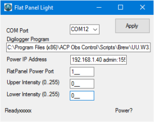
- The COM port is the one assigned by the Arduino IDE when it communicates to the Arduino.
- The power cord to the light panel is controlled through a Digilogger IP power switch.Two special values are used to control power: a value of 0 turns the power off, and a value of 255 turns the power on. These values are hard-coded in the ACP AutoFlat script. The DigiLogger Program, IP address, and Port are used to perform these power operations.
- The program stores its settings in a config file. Establish the settings by running FlatPanel manually, setting the values, and exiting the program.
- Subsequently FlatPanel can be run like a console program. If the runstring has an argument (for example, 255) then the Arduino is set to the argument value and the program exits without displaying an interface. This is the mode used by the AutoFlat script. If the argument happens to be 255 the power is turned on; a value of zero turns the power off.
- The two panel values are sent to the Arduino, with the two bytes combined into a single integer. The value of that integer is displayed in the label at the lower left of the screen. These integers are used in the settings placed in the AutoFlatConfig.txt file.
AutoFlatConfig.txt file Settings
I manually determined the values for each filter/bin combination so that a flat image requires about a 1 second exposure. These settings are then entered into the AutoFlatConfig.txt file. My settings for this portion of the AutoFlatConfig file are:
; Starting with ACP 8.1 you can specify separate panel brightness values
; for higher binning, accounting for the higher sensitivity at those
; binning levels.
;
; Lum R G B Ha Oiii Sii
PerFilterBrightness 22, 70, 65, 75, 65530, 65530, 65530
PerFilterBrightnessBin2 6, 20, 20, 20, 41210, 65335, 65530
PerFilterBrightnessBin4 1, 5, 4, 4, 50, 50, 50
;
LightCtrlProgram D:\Dropbox\BrewSky\Programs\FlatPanel\FlatPanel\bin\Debug\FlatPanel.exe
LightOnCommand #BRT#
LightOffCommand 0
LightOnDelay 2 ; Time needed (sec) for brightness to stabilize