
I have suddenly become interested in planetary photography. I have an ASI290MC to use, so I have been setting up to do this. As part of this I wanted to redo the collimation on my Celestron Edge 11″. I did it several years ago and haven’t touched it since; the scope is permanently mounted in the observatory so I didn’t think it should change much. Since this is so critical for planetary imaging, it is time to redo it.
The first attempt was a big failure. I couldn’t figure out which way to turn the adjustment knobs, and I kep changing what I thought they did. I was also unclear as to what CCDInspector was telling me. After a couple of hours I have messed up the collimation to the point that the donut does not have a visible hole:(
Started over again the next night.
Setup: 290 is set as Camera1 in Maxim. Dome and slewing are connected in theSkyX rather than the usual ACP. CCDInspector is calculating images as they are taken.
Other people seem to be working with images after they have been taken somehow. They take 20 images into a folder and then have CCDInspector work on those images. They also use the Curvature plot to access the collimation tool. I could not get that process to work.
Because everything was so messed up from the previous night I did a (rough) visual collimation with an eyepiece using Vega as the target star (nice and bright so I can find it). Played with it visually until it looked pretty good with a centered donut. The donut is huge, I am well out of focus. Once collimation is set I do not expect future attempts to need this step.
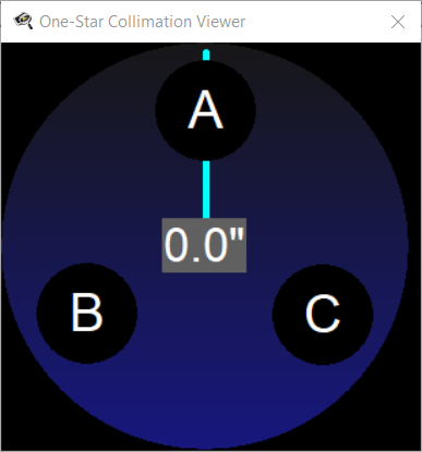
Now replaced the eyepiece with the 290 and switched to CCDInspector and its collimation tool. I am using the Defocused Single Star mechanism. The tool starts with the window
Worked on getting the rules for the knobs straight:
- Checked that the top of the sensor is at the top of the OTA. Put my hand over the tube front at the top of the OTA, verified that the “shadow” on the screen is at the top of the image. I don’t understand why this is necessary, won’t the shadow always show up at the top regardless of how the camera is rotated? Anyway, I read somewhere that you should do this, so I verified the shadow was correct.
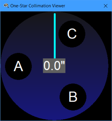
- Rotated the knob positions on the tool to match the positions of the knobs as viewed from the front of the OTA.
- Checked where the knobs were by putting a wood stick in front of the OTA by each knob. The stick at the A position darkened the image on the left, matching the A position. However, the stick at position B darkened the image at C, and the stick at C shadowed at B. I think this led to much of my earlier confusion; the B and C knobs are mirrored from where the shadows appear. I think this step is unnecessary, and likely confusing. The map created next is the correct step.
- Centered the star. It is important to center the star all the time before reading the tool data; otherwise a) you get poor readings, and b) you get all these error messages about the star being too dim / bright / deformed. You need to get the star fairly precisely centered before looking at anything the tool tells you. The Maxim cross-hairs help.
- Create a map on paper showing what the knobs do. For each knob, loosen the other two knobs and tighten the target knob. It only takes a VERY small adjustment, especially on the small chip of the 290 camera.
- The star will shift on the screen; you need to move it enough to be clear on which way it moves, but don’t let the star move completely off the screen.
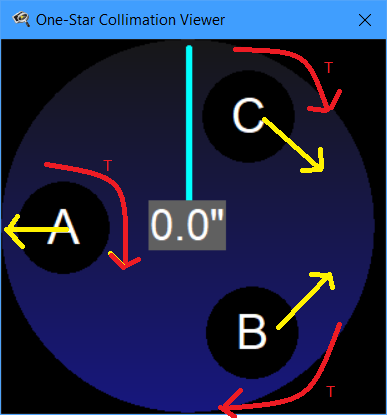
- Once you know which direction the star shifts on the screen, mark your map. For example, when I tightened B (with corresponding loosening of A and C) the star moved up and to the right. The star did not move toward B. I mark the red arrow with T (tighten) and draw the yellow arrow indicating which way the star moved.
- Recenter the star and repeat for the next knob. My map looked like
I set the Settings/Default Image Properties to match my system so the results might be in arcseconds. I also set Real-Time/Images to Average to 3 to smooth out the readings. The seeing was poor, so the values tended to be erratic. I set Maxim to run continuous 1 second images, so the tool constantly updates while I am on the ladder adjusting knobs.
Now I can do the collimation. When a reading is successfully taken the tool’s big circle will momentarily turn red. The blue line indicates the direction of the mis-alignment. Here is the key: you want to adjust the knobs so the star moves in the direction the blue line is pointing.
For example, in the map image above the blue line points straight up. This would indicate I want the star to move upward. To do this I need to Tighten B and Loosen C. Loosening C makes a vector pointing up and to the left; combining this with B going up and to the right yields a net movement of up. Often you only need to adjust one screw; for example, if the blue line points to 9 o’clock I need to tighten A. This requires loosening B and C to allow A to tighten.
After adjusting, let the system calm down a bit before trusting the tool’s values.
With the poor seeing I was only able to get the collimation to 4.5-5. At that point the arrow basically randomly swept around the dial.
Supposedly, the star’s brightness should not matter for this process. However, I switched to a slightly dimmer star (Deneb) and repeated the process. I was able to get a slightly better result, 3.5-4. This may have been random rather than due to the dimmer star. Supposedly people are getting values < 1; maybe they have better seeing?
Next step: I want to try MetaGuide to see how it compares.