
The continuing saga of the shutter controller…
In the process of testing capacitors on my controller, I somehow managed to plug power in backwards. Thought I had fried everything (Arduino Mega 2560, cc3000, and MonsterMoto shield). In the end, it turns out all that fried was the SWADJ3 voltage regulator.
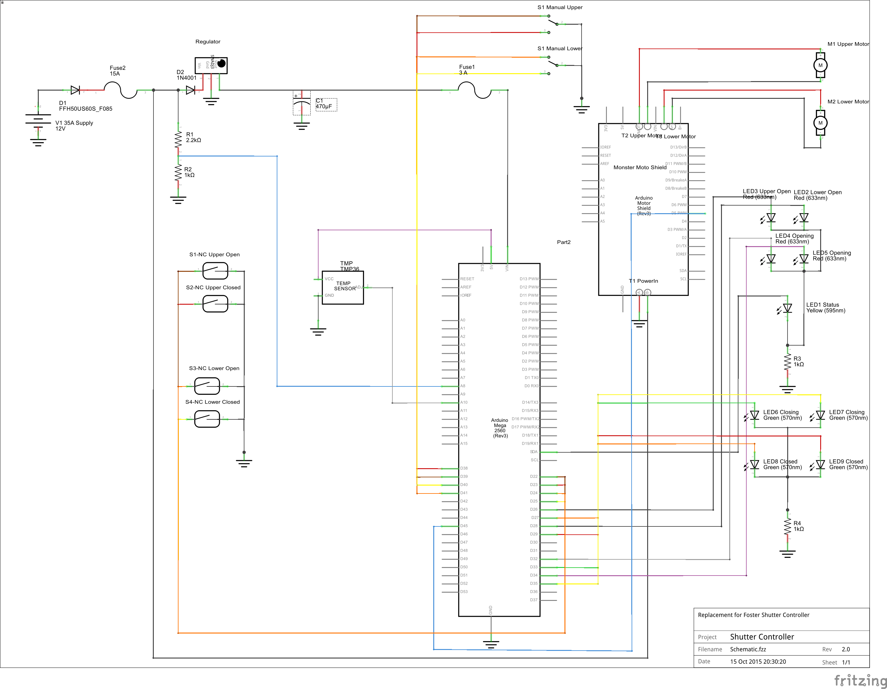
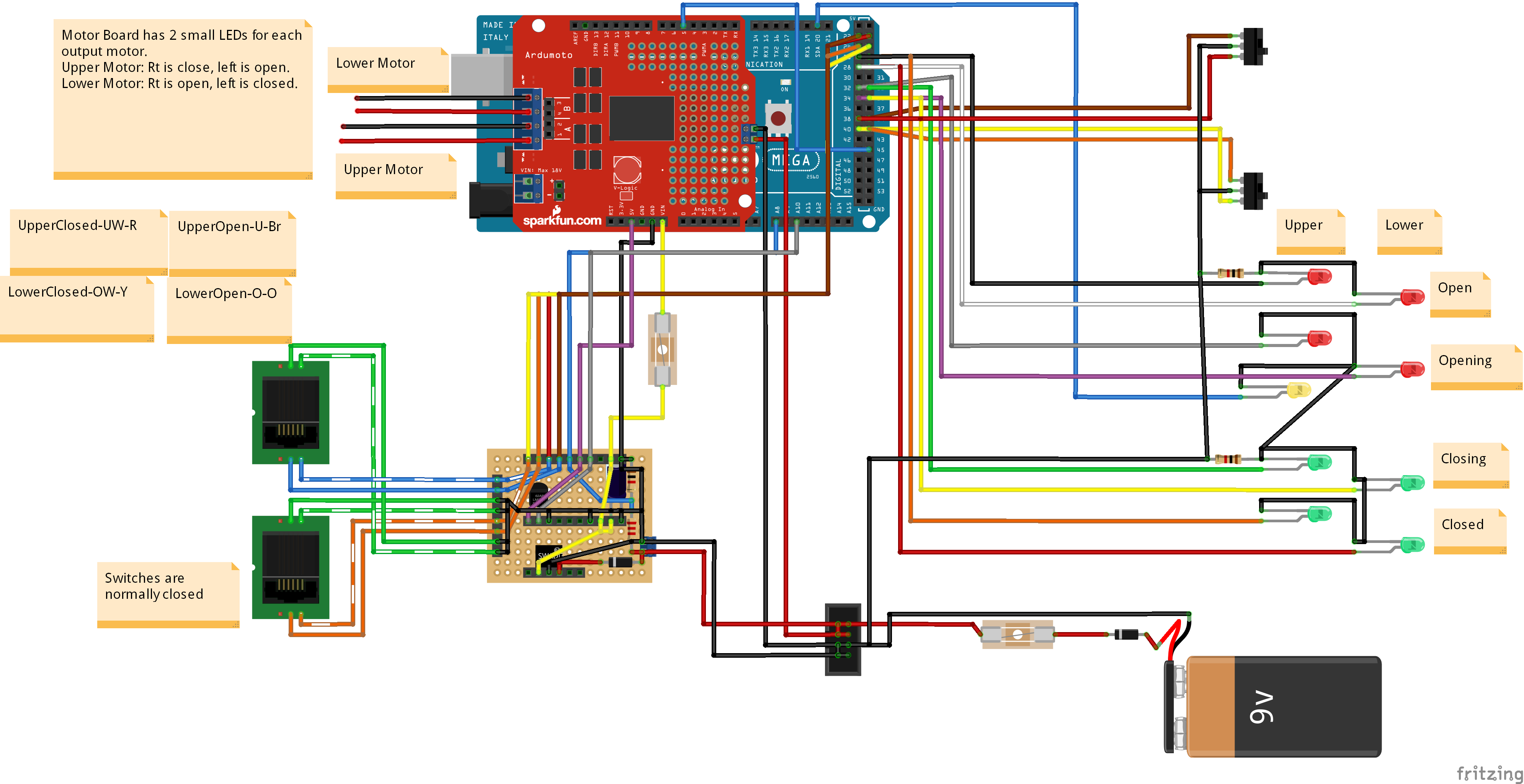
So, I rebuilt the small PC board to account for a couple of changes:
- Added a couple of diodes to protect from idiots plugging in power backwards. The Arduino power branch has a regular N4001 diode; that path shouldn’t be seeing a lot of current. The other diode is a Power diode, handles 50A at 200V or something. Big thing, 3/4 inch square.
- Added headers to allow connection to SWADJ3, capacitor, switch input wires. This should allow changing things without having to unsolder wires.
- Added capability to add 2 capacitors after the voltage regulator, so I can play with trying to fix the original problem.
I also changed the controller logic to remove the ramping up of the PWM for the motors. I just apply full voltage to the motors.
The new schematic and wiring diagram are here:
The Problem (Review)
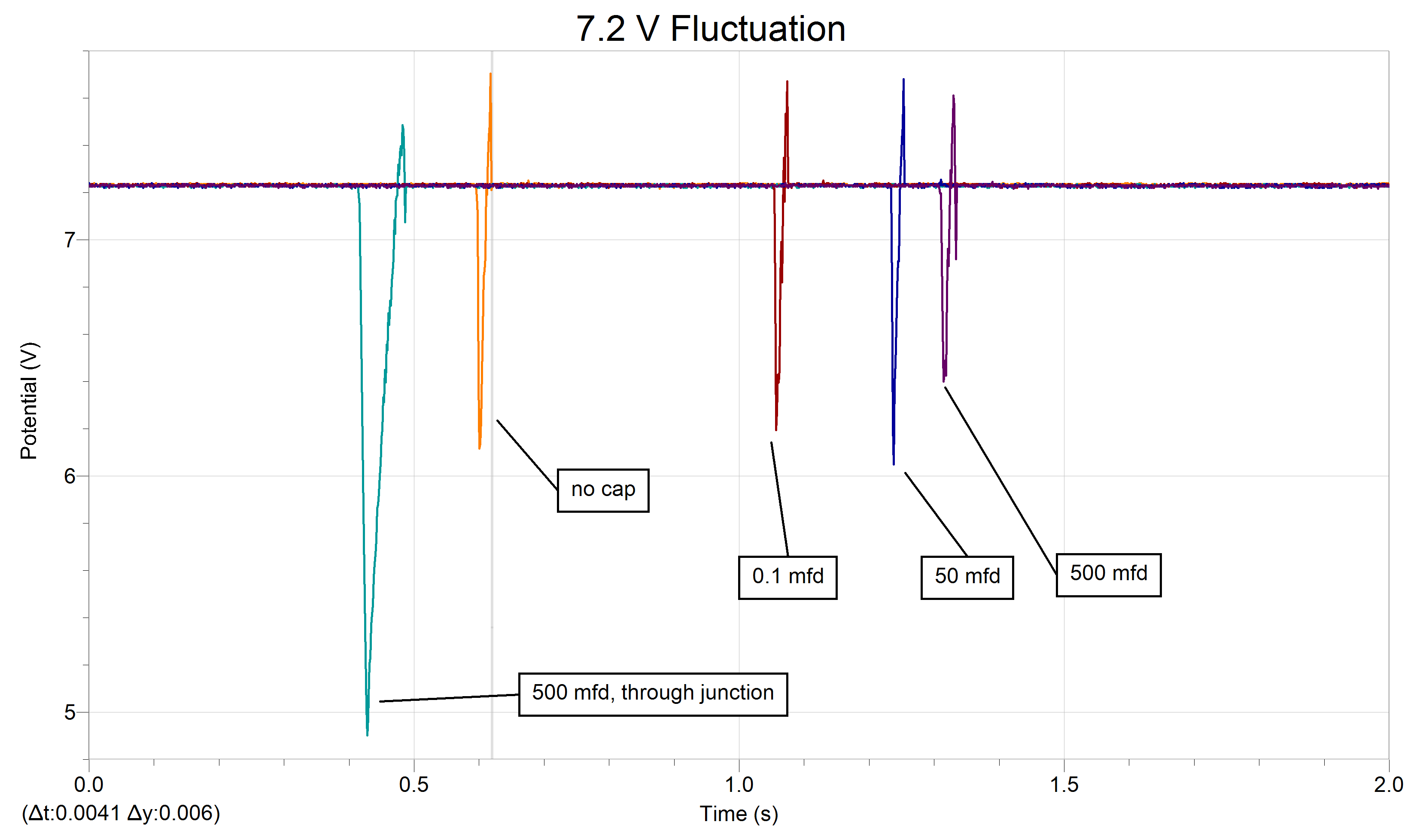
The problem I am chasing: when the shutter motors are activated the overall voltage in the system plummets drastically as shown in the data below. The upper shutter doesn’t drop quite as much. Opening the lower shutter is worse than the upper shutter, but is OK (system doesn’t seem to fail). However, closing the lower shutter drops the voltage the most. Sometimes, this drop causes the Arduino to reboot, so the shutter never moves.
Oddly, running the voltage directly into the controller does not lead to as large a voltage drop, so generally the shutter does not fail. However, running the power in through the contact junction causes a bigger voltage drop, leading to frequent failures. I don’t know why this is. I measured the resistance of the junction: 0.7 ohms through the red wire, 1.1 ohms through the black side.
Solution?
I tried a variety of capacitors before the regulator and after the regulator. As seen above, none of these seemed to help. In particular, running through the junction contacts causes a very large voltage drop.
In discussions on the SAC forum, it was suggested that my capacitors may be too old. OK, they are probably 30-40 years old… So I went to Radio Shack and picked up a couple of new ones. For power applied directly to the controller, the effect was dramatic! A small blip could be seen, but nothing like the previous situation.
Unfortunately, running power through the junction contacts is better, but still pretty severe. I am concerned that as the dome rotates the contacts may have better or worse contact, still leading to intermittent problems.
I cleaned the copper surfaces, and re-fastened one of the connecting cables to try and improve the connectivity. This helped a little bit. Now the voltage drop is not as severe – it is not going below 5 volts, at least.
Future Possibilities
I am hoping that these changes will allow the shutter to operate successfully. If the problem continues, the following options might be useful.
- Maybe I should adjust the SWADJ3 regulator to a higher voltage. I currently have it at 7.2 volts; perhaps if I run it up to 8.0 volts this will raise the dropped voltage the corresponding amount. This leads to more heat dissipated in the Arduino, but perhaps that is not a problem.
- Maybe I should experiment with moving the 470 uF capacitor back before the regulator. Forum members have suggested both cases, before and after the regulator. I don’t know why one or the other would be better.
- If I understood why the junction causes a problem, perhaps I could redesign it to fix it.
Thoughts on Junction Voltage Loss
The Arduino typically pulls less than 200 mA in normal mode – motors not running, checking for communications every second. In this mode, a 2 Ohm resistance in the junction would give a 0.4 volt drop. Thus, the input 12.8 Volts might be dropped to 12.4 V. This voltage would be constant, and the regulator would easily drop it to 7.2V for the Arduino.
However, when the motor kicks in it pulls perhaps 3-4 amps? 4 Amps would give an 8V drop, leaving only 4 V going into the regulator. It sounds like I need to redesign the junction with much less resistance…